Arduino Distance Measurement Using Ultrasonic Sensor

By // 3 comments:
We all know about the ultrasonic sensor and also wanted to play with it, but don't know how ultrasonic sensor works. So In this article, we will see  how to use an ultrasonic sensor with your projects. The ultrasonic sensor is very popular among arduino hobbyist and there are so many projects which you will be able to do at the end of this article.

Description of HC-SR04 Ultrasonic Sensor
ultrasonic sensor
Ultrasonic Sensor can measure the distance from 1" to 13 feet( 1 cm to up to 4metre) with accuracy up to 3mm. A hc-sr04 ultrasonic sensor has 4 pin GND, VCC, Echo and Trigger Pin. Trig pin generate an ultrasound by setting trig pin on the high state of 10 microseconds. Echo pin produce an output in a microsecond when ultrasound returns back from the object to echo pin.

We can calculate the distance by using simple formula Speed=(Distance/Time). The speed of the sound is 340m/s and thus by calculating ultrasound travel time we can calculate the object distance from the ultrasonic sensor.

Required Components
  1. 1 Arduino UNO board( Buy from here Arduino )
  2. 1 HC-SR04 ultrasonic sensor ( Buy from here sensor )
  3. Jumper wire
  4. Breadboard

Circuit Diagram
Ultrasonic sensor pin connected to arduino pin in a very simple manner as shown in the image below. Here we use a voltmeter as a reference because we can't place a real object before the LDR. So when we increase or decrease the voltage level of voltmeter then its corresponding value also changed.
Arduino           Ultrasonic sensor
Vcc                      Vcc
Pin 5                   Trig
Pin 4                   Echo
Gnd                     GND 
ultrasonic_sensor circuit
Circuit
Source code
Here first we define the trig pin and echo pin of the ultrasonic sensor and they are pin no 5 and pin no 4 respectively. Here we define Trig pin as output and Echo pin as an input. After that, we defined three long variable name duration, cm and inches. In the loop first we set the Trig pin Low for few microsecond and after that, we set it in the high state for 10 microseconds. We read the travel time by ultrasound by using the pulseIn() function.
ultrasonic sensor source code
Source Code
For getting the exact distance we multiply .034 in duration and then divide it by 2 because ultrasound travels forward and backward. At the end we use Serial.print() function to print the value in the virtual terminal.You can download the source code by clicking on the link.

Video Demonstration 


Hope you like this tutorial on the ultrasonic sensor. If you have got any problem using the ultrasonic sensor or its proteus simulation then feel free to comment below or if you have any suggestion about this tutorials and let me know by your valuable comments. 

How to Interface 4*3 Keypad With Arduino

By // No comments:
In this article, we will find out how to interface a matrix keypad with arduino in very easy technique. During this article, we are using a 4*3 matrix keypad. Keypads are a very important component in the embedded system which are used in various mini or major comes and the commercial product like telephone, electronic locker, and alternative automation product. At the end of the article you may be ready to interface a matrix keypad together with your arduino and after you press a key, its shows up into the serial monitor.

What is 4*3 Matrix Keypad
One of the most frequently asked question among the students or hobbyist are when we use 4*3 or 4*4 matrix keypad and what is the difference between them. Therefore, we have only one answer what's your requirement within the project. The logic behind operating of each keypad are same. The 4*3 keypad is simple keypad having 4 rows and 3 column, therefore, total 12 keys as shown in the image. There are so many distributors wherever you will purchase a keypad otherwise you can purchase from here
type of keypad matrix 4*3 Keypad matrix 

Circuit Diagram
The circuit of interfacing of a keypad with arduino is very simple. You only need to connect rows 1, 2, 3, 4 to digital pin 6, 7, 8, 9 respectively and column 1, 2, 3 are connected to digital pin 10, 11, 12 respectively of the arduino. The circuit is extremely easy to grasp as shown in the below image.
simple circuit diagram of keypad interfacing with arduino
Circuit Diagram
Program

Program of interfacing a keypad with arduino is extremely easy. Here we simply use an if-else statement to check every condition one by one. First we kept row 1 low and check all condition for it and equally with others rows one by one. You can download the source code from here.
From here you will display the key on an LCD and build a lot of other cool projects like door lock, calculator, security system enabled projects. Hope you like this article. If you have got any doubt then comment below or have any suggestion then you may be forever welcome to ProjectsDunia.

VIDEO:


555 Timer IC: Introduction, Working and Pin configuration

By // No comments:
One of the most versatile linear integrated circuit is 555 timer. 555 timer IC was first introduced in early 1970 by  Signetics Corporation.555 timer IC is incredibly low cost and popular timing IC that is used by electronics student, hobbyist for generating timing delay and pulses. Mono stabale and astable multi vibrators is that the most correct example of its application. With the exception of this it's conjointly used for oscillations, waveform generators, analog frequency meters, voltage regulators, digital  probes, tone generation, frequency divider and lots of others.This device is obtainable as 8-pin mini Dual-in-line package(DIP)  or 14 pin Dual-in-line package(DIP) that consist 25 transistor,16 resistors, 2 diode.

PIN CONFIGURATION OF 555 TIMER IC
555 timer ic pin configuration
8-Pin DIP 555 Timer IC

Pin 1: Ground   This pin is used to measured the all voltages.

Pin 2: Trigger   Negative going pulse is applied to this pin whose dc level is greater than 1/3 times                                VCC. Thus comparator 2 output goes low. The output remains high as long as                                      trigger terminal is held at low voltage.

Pin 3: Output    Output pin is available to connect the load.There are two ways of connecting the                                   load either between pin 3 and ground or between pin 3 and +Vcc pin of 555 timer                                 IC.

Pin 4: Reset      555 timer can be reset by applying a negative pulse to this pin.

Pin 5: control voltage  To change the threshold voltage and trigger voltage an external voltage is                                               applied to this pin.

Pin 6: Threshold  SR flip flop is reset when voltage at this pin is greater than 2/3 Vcc.

Pin 7: Discharge   This pin is directly connected to the collector of transistor.When transistor is off                                     this acts as a open circuit and when transistor is on, acts as a shot circuit.

Pin 8:   A Supply voltage is applied to this pin that ranges from +5v to +18v with respect to                              the ground.

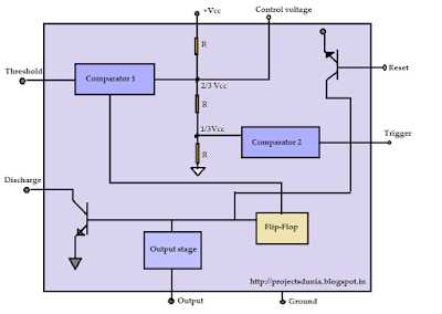
Block Diagram of 555 Timer IC

555 timer ic block diagram image
555 Timer IC Block Diagram

The 555 timer IC work as a mono-stable multi-vibrator and astable multi-vibrator. A voltage divider circuit is internally connected to the Pin 8 and Pin 1 of 555 timer IC. This circuit hold positive non inverting terminal of comparator at 1/3Vcc and negative inverting terminal of comparator at 2/3Vcc. The output from each comparator is connected to the input of the SR Flip-Flop. The output from the SR Flip-flop acts as a switching stage to drive the Load.

555 Timer IC has three operative modes known as:
1: Monostable
2: Astable
3: Bistable

To Know additional concerning 555 IC Click on this 555 Data sheet.

How To Interface Relay With Arduino

By // 2 comments:
A Relay is an electromagnetically operated switch. Relays are used to control a circuit. Many relays consist a coil, a yoke, and an armature. When a current is passed through the coil, a magnetic field is induced in the coil which moves the armature and relay start its switching function. A normal relay has NO(normally open), NC(normally connected), COM and coil pin within it. A Simple one channel relay is shown in below image
relay driver interfacing
Relay
Required Components
For designing a relay driver circuit you will need following components 
  • Relay
  • 1N4007 Diode
  • BC547 Silicon NPN transistor
  • 10K Resistor 
Circuit Diagram
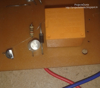
A simple relay driver circuit is shown in below image. Here we use an NPN BC547 transistor to drive the relay.Base current ought to be a lot of enough to turn on a transistor. A diode 1N4007 use among the circuit to protect the transistor from damage due to back emf. When relay is in off state, COM pin of 

circuit diagram of relay driver
Relay Driver Circuit 
a relay is connected to NC(normally connected) pin and when a small current start flows through relay coil then COM pin is connected to NO(normally open) pin.

NOTE: Change +5V  to +12V in the circuit 

Code for relay testing is same as for blink an LED so learn  how to blink an LED and test your relay driver circuit. Now using relay make some more cool projects using arduino like control your AC home appliances, turn ON/OFF a bulb and many more.

Hope you like this article and give your valuable feedback by commenting below or if you have got any problem then also comment below. 

How To Interface LDR With Arduino

By // No comments:
Hello, Friends hope all of you playing with your arduino and currently need to try to do another cool projects on arduino. Therefore, this tutorial is for you. During this tutorial, we interface LDR(Light dependent Resister) with the arduino board. It is very simple tutorials for arduino students, hobbyist, and beginners. Before going more we must find out how LDR is dependent on Light.

What is LDR 
interfacing ldr with arduino
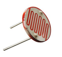
LDR(Light dependent Resister) or a photoresistor is a light dependent variable resistor that resistance decreases with the increase in the intensity of light. This gives an analog value so that it is connected to an analog pin of arduino board. A simple LDR is shown within the image and to buy an LDR click on the below image

Circuit Diagram
A simple circuit diagram is shown in the image. We won't use LDR directly within the circuit in order that a potential divider circuit is used with a 10K resistor. In this circuit one pin of LDR is connected to Analog pin A0 of arduino UNO and one pin is connected to ground(GND).

circuit diagram of LDR interfacing with arduino
LDR Circuit
Source code
Now connect your arduino board together with your PC and upload the given source code into the board. After uploading the code run your program and see the different value in your serial monitor.

LDR interfacing source code with arduino
LDR Code
Download:


Watch This Video:


How To Display Custom Characters On LCD Using Arduino

By // No comments:
We all are aware of custom characters used in the various display module.Heart, various style of smileys, arrow are the foremost usually used custom characters. Thus, during this tutorial, we are going to learn how to display custom characters in LCD using arduino UNO board. This project is done by using of arduino UNO board and 16*2 LCD module.

how to display custom character in lcd using arduino
Custom Character Display
It is assumed that reader knows how to interface LCD with arduino and how to install arduino software.We can generate a completely different style of the custom character using the below pixel array shown in the image. 
use of pixel array of lcd
Pixel array
the custom character shown below that is used in our program to generate the smile type character:
         {
                0b00000,
                0b00000,
                0b01010,
                0b00000,
                0b10001,
                0b01110,
                0b00000,
                0b00000
              };

Circuit diagram:
circuit diagram of display custom character in lcd
Circuit Diagram
Source Code:


Download:


Video: