Showing posts with label sensor. Show all posts

How To Interface PIR Sensor With Arduino

By // 14 comments:
Hello Arduinians... Ever thought of detecting motion via your Arduino.... if yes, then this one's for you. In this tutorial, We're interfacing PIR sensor today with Arduino. Let's gets started!

Block Diagram
Working of PIR Motion Sensor
Block Diagram
Components Required For This Tutorials
  1. 1 * Arduino Board
  2. 1 * PIR Motion Sensor(you can buy from here)  
  3. Breadboard
  4. Jumper wires
  5. Battery

What is PIR motion sensor & how it works?

Basically, a PIR stands for "Passive Infrared Sensor". The sensor works on the principle of infrared waves' detection those are being emitted by human bodies. They are undetectable to us but can be discovered by the devices designed for such special purposes. I'm going to go just a little deep, enough to make you understand the internal operation.
When a body moves in front of a PIR sensor, the temperature of that place changes where the body has moved. If the body makes a further movement, the composition of infrared waves being received by the PIR from that region changes and since the reading is not the same as last reading, it generates a signal for the microcontroller and we work on it accordingly.


Circuit Diagram
We can easily interface PIR motion sensor with Arduino-like our other sensor. But it all depends on our logic of the code, how efficiently do we want to detect motion through it.
A PIR has 3 pins, just like any other sensor, Vcc, Signal & Ground pin. A very simple circuit of interfacing PIR motion sensor with Arduino is shown below
circuit diagram of PIR Motion Sensor
Circuit 
PIR Motion Sensor description
                                                                                          PIR Motion Sensor                                          
The 2 knobs are there too. One for adjusting sensitivity by increasing or decreasing the range of motion detection and another one for response delay. If you're using PIR in your home security, I strongly suggest you set the range at maximum (towards right). However, the detection range offered by a PIR sensor is good enough, like about 6 metres as I've tested it successfully.

Source Code
Here is a very simple code for this tutorial which only detects if there is ANY motion and triggers an LED for confirmation.Write below code into Arduino IDE and compile it.

int pirSensor=5;                                                     // connect sensor at pin 5
int led=13;                                                             // connect led at pin 13
void setup() 
{
   Serial.begin(9600);                                             // initialize serial
   pinMode(led, OUTPUT);                                  //  initialize led as output
   pinMode(pirSensor, INPUT);                            //  initialize sensor as input  
}

void loop() 
{
  int sensorValue = digitalRead(sensor);                // read sensor value
  Serial.println(sensorValue);                                 // print sensor value  
  delay(100);                                                          //  delay 100 miliseconds
  if(sensorValue > 600)
  { digitalWrite(led,HIGH); }
}

Now you can connect the signal pin to any analog pin also but for that, you'll have to check what values do you get on the serial monitor and which value do you wish to use as a threshold for triggering any LED, buzzer, etc.
Note that the sensor first takes some time for its calibration and after that it starts detecting motion. If any motion is detected, it triggers the LED on Arduino board and keeps searching for the motion for a certain amount of time. It only settles low if there is no further motion detected for that given search period (which can be changed in code). Giving a search window to your sensor, makes it's working more efficient and there are better chances for you to get non-erroneous functioning.
I too did both codes and both worked fine for me. Here's a snap!
PIR motion sensor circuit
Demo
So that's an end to our tutorial  for this time. Hope you enjoyed reading. If you liked this tutorial then don't forget it to share with your friends. I'll be back with more..... till then #happyDIYing

If you have any question or query or feedback regarding this tutorial then leave a comment below and we will solve those as soon as possible.

Be sure to buy the stuff mentioned in this blog by clicking on the link below-
http://www.ebay.in/usr/4d_innovations?_trksid=p2053788.m1543.l2754

The vendor's offering interesting and working hardware at quite handy rates. Go give it a try! :)

A Guide For Interfacing Analog Sensors With Arduino

By // 6 comments:
With Arduino, almost everything seems to be too friendly when it comes to interfacing various sensors, shields, add-ons or any other utility devices. Just because the Arduino coding environment is so user-friendly, anyone can do it. So in this post, I will just show you how to hook up your sensors to Arduino and get them running. Let's start with the very basics....

sensor interfacing with arduino
Sensors
What is Sensor
Sensors are those electronic components which convert physical data into electronic data. This data is in analog format and is fed to the microcontroller on the Arduino board. The microcontroller has inbuilt ADCs (Analog-2-Digital Converter) which processes this data and converts it into digital format.

And once you have received the (electronically converted) physical data, you can make your Arduino perform as you want.


On your Arduino board, there are analog pins named as A0, A1, A2, A3, A4, A5. The number of these pins may vary depending on your Arduino board. For UNO, there are only 6 analog pins while for MEGA there are 16. And remember this thing, any sensor (or other components) that gives analog data and you wish to process it, you'll have to connect it to your analog pins only. For now, I would say SENSORS would always be connected to analog pins.

Connection of Analog Sensor with Arduino
All sensors have their own method to connect with Arduino. Some of them need pull-up resistors, some need a certain power supply to use them.  But any sensor has generally 3 pins to connect to Arduino or other development board. These pins are. 
1. +Vcc
2. Signal
3. Gnd
Hook up the +Vcc to 5v (or 3.3v if sensor demands it) on your Arduino board.
Connect the Gnd pin to Ground pin on your Arduino.
Connect the Signal pin to any of your Arduino's analog pins. In our case, say A1.

Code for Interfacing Analog Sensor with Arduino
Below code is general code for interfacing analog sensors with Arduino. Write this code in your Arduino IDE to start playing with analog sensors.
void setup()
 {
  Serial.begin(9600);                            // initialize serial communication at 9600 bits per second:
  }

void loop() 
{
  int sensorValue = analogRead(A1);            // read the input on analog pin 1:
  Serial.println(sensorValue);                       // print out the value you read:
  delay(1);                                                      //this  delay in between reads for stability 
}

After burning this code to your Arduino, open the serial monitor and see the analog-2-digital converted data on your serial terminal. Basically, it is 10-bit data since the inbuilt ADC of your Arduino is a 10bit ADC.You will get the reading on your serial monitor.

That's all for now. Hope you got everything out of that blog.I'll try to bring something new next time. Till then........ keep learning and keep prototyping.

If You have got any problem or feedback then comment below. I will be right back to you soon.

Be sure to buy the stuff mentioned in this blog by clicking on the link below-

The vendor's offering interesting and working hardware at quite handy rates. Go give it a try! :)

Automatic Street Light Controller Circuit Using LDR And 555 Timer IC

By // 54 comments:
We are living in the world where everything goes to be automatic from your washing machine to your ceiling fan. Street lights are one of those examples of the automatic world. Automatic street light are those light which needs no manual operation to gets turn ON and turn OFF. Did you ever try to make such kind of street lights that gets turn ON and turns OFF automatically? In this article, we are going to make automatic street light using LDR and 555 timer IC.

List of Components  
  1. 555 Timer IC
  2. LDR
  3. LED
  4. Potentiometer
  5. Resistor 1* 1k ohm 
  6. Resistor 1* 220 ohm
  7. 9V Battery
  8. Printed Circuit Board(PCB) Or BreadBoard 
Circuit Diagram
A very simple circuit diagram of automatic street light is given below. 
automatic street light controller circuit using ldr
Automatic Street Light Controller Circuit

Principle and Working of Automatic Street Light Controller

555 Timer IC is the main part of the circuit that works as a comparator. All the working of this circuit depends on the working of the 555 timers Ic.To know more about 555 times IC read this article Working of 555 Timer IC. In this circuit pin, 3 produce output which has just two states high and low. Output goes to high when  trigger pin  is at a lower level than the 1/3rd level of the power supply voltage and output goes low when trigger pin 2 is at above then 1/3rd  of the power supply voltage. In this circuit pin, 4,6 and 8 are connected to the power supply. Here we use LDR to detect the presence of light which is formed a potential divider circuit with the help of 1k ohms resistor. LDR is a special type of resistor whose value depends on the light. Read this article to know How LDR Works. The output of this divider circuit is given to trigger pin of the 555 timer IC. 

In this circuit, we use a simple LED to know how the whole circuit works. You can also connect as much led as you want by using the transistor or you can connect a Relay to control high voltage electrical bulbs. 

You must use caution while connecting Relay to this circuit because its may be danger and as different bulb have different wattage.

Video Demonstration of Automatic Street Light Controller


Arduino Distance Measurement Using Ultrasonic Sensor

By // 3 comments:
We all know about the ultrasonic sensor and also wanted to play with it, but don't know how ultrasonic sensor works. So In this article, we will see  how to use an ultrasonic sensor with your projects. The ultrasonic sensor is very popular among arduino hobbyist and there are so many projects which you will be able to do at the end of this article.

Description of HC-SR04 Ultrasonic Sensor
ultrasonic sensor
Ultrasonic Sensor can measure the distance from 1" to 13 feet( 1 cm to up to 4metre) with accuracy up to 3mm. A hc-sr04 ultrasonic sensor has 4 pin GND, VCC, Echo and Trigger Pin. Trig pin generate an ultrasound by setting trig pin on the high state of 10 microseconds. Echo pin produce an output in a microsecond when ultrasound returns back from the object to echo pin.

We can calculate the distance by using simple formula Speed=(Distance/Time). The speed of the sound is 340m/s and thus by calculating ultrasound travel time we can calculate the object distance from the ultrasonic sensor.

Required Components
  1. 1 Arduino UNO board( Buy from here Arduino )
  2. 1 HC-SR04 ultrasonic sensor ( Buy from here sensor )
  3. Jumper wire
  4. Breadboard

Circuit Diagram
Ultrasonic sensor pin connected to arduino pin in a very simple manner as shown in the image below. Here we use a voltmeter as a reference because we can't place a real object before the LDR. So when we increase or decrease the voltage level of voltmeter then its corresponding value also changed.
Arduino           Ultrasonic sensor
Vcc                      Vcc
Pin 5                   Trig
Pin 4                   Echo
Gnd                     GND 
ultrasonic_sensor circuit
Circuit
Source code
Here first we define the trig pin and echo pin of the ultrasonic sensor and they are pin no 5 and pin no 4 respectively. Here we define Trig pin as output and Echo pin as an input. After that, we defined three long variable name duration, cm and inches. In the loop first we set the Trig pin Low for few microsecond and after that, we set it in the high state for 10 microseconds. We read the travel time by ultrasound by using the pulseIn() function.
ultrasonic sensor source code
Source Code
For getting the exact distance we multiply .034 in duration and then divide it by 2 because ultrasound travels forward and backward. At the end we use Serial.print() function to print the value in the virtual terminal.You can download the source code by clicking on the link.

Video Demonstration 


Hope you like this tutorial on the ultrasonic sensor. If you have got any problem using the ultrasonic sensor or its proteus simulation then feel free to comment below or if you have any suggestion about this tutorials and let me know by your valuable comments. 

How To Interface LDR With Arduino

By // No comments:
Hello, Friends hope all of you playing with your arduino and currently need to try to do another cool projects on arduino. Therefore, this tutorial is for you. During this tutorial, we interface LDR(Light dependent Resister) with the arduino board. It is very simple tutorials for arduino students, hobbyist, and beginners. Before going more we must find out how LDR is dependent on Light.

What is LDR 
interfacing ldr with arduino
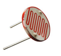
LDR(Light dependent Resister) or a photoresistor is a light dependent variable resistor that resistance decreases with the increase in the intensity of light. This gives an analog value so that it is connected to an analog pin of arduino board. A simple LDR is shown within the image and to buy an LDR click on the below image

Circuit Diagram
A simple circuit diagram is shown in the image. We won't use LDR directly within the circuit in order that a potential divider circuit is used with a 10K resistor. In this circuit one pin of LDR is connected to Analog pin A0 of arduino UNO and one pin is connected to ground(GND).

circuit diagram of LDR interfacing with arduino
LDR Circuit
Source code
Now connect your arduino board together with your PC and upload the given source code into the board. After uploading the code run your program and see the different value in your serial monitor.

LDR interfacing source code with arduino
LDR Code
Download:


Watch This Video:


How to Use A Temperature Sensor With Arduino

By // 8 comments:
A thermometer is a device measures the temperature. A Thermometer consists a temperature sensing element that senses environment temperature and provides the result to the suitable devices. During this article, you may tend to learn to make a digital thermometer using LM35 temperature sensor and LCD module display.For LCD interfacing with arduino read this article Interfacing LCD With Arduino UNO  

LM35 :

LM35 temperature sensor
LM35 Temperature Sensor 
LM35 is a temperature sensor that is employed to measure the temperature. It has three terminal Vcc, Output, Ground as shown in the above image 
The range of the LM35 temperature sensor is from -55 'C to +155 'C. The output range varies by 10mV to each fall and rise in temperature. Circuit diagram of Digital Thermometer using LM35 temperature sensor with arduino UNO is shown below: 

Automatic Temperature Fan Speed Controller 

Circuit diagram

It has a very simple circuit. The output terminal of the sensor is connected to the analog pin A0 of arduino board. Vcc and GND pin of the sensor are connected to the power supply and GND respectively. 
circuit diagram of digital thermometer
Digital Thermometer Circuit Diagram


Program
arduino code of digital thermometer with LM35
Code For Digital Thermometer
Download


Video