Showing posts with label proteus. Show all posts

Learn How To Make A Digital Voltmeter Using Arduino

By // 12 comments:
Arduino is very popular and easy to use. With Arduino, we can do lot's of projects and experiment. So today we add one more projects in our Arduino project list. In this article, we are going to make a digital voltmeter.using an Arduino board. In this project, we measure the input voltage range between 0 to 50V by using the voltage divider. It is very simple to use Arduino as a voltmeter. Arduino UNO has  5 analog pin to read the input analog value. If we have an idea about reference voltage then we can easily measure the input voltage. Here we will use 5V as a reference voltage.
Block Diagram
arduino based dc voltmeter circuit diagram
Block Diagram of DC Voltmeter
Component Required 
  1. 1 * Arduino Board(In this article we use Arduino UNO)
  2. 1 * LCD Module(Here we will use 16 * 2 LCD Module)
  3. 1 * 100K Resistor 
  4. 1* 10K Resistor
  5. 1 * 5K Potentiometer
  6. Some jumper wires
  7. Breadboard 
Circuit Diagram
Circuit diagram of this projects is very simple and easy to understand. Here we use a 16 * 2 LCD module to display the voltage. Read this article to learn How To Interface LCD With Arduino UNO.
arduino based DC Voltmeter circuit
Circuit Diagram
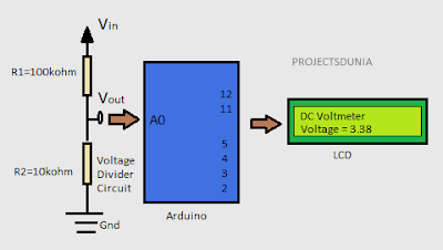
A voltage divider circuit is used here to divide the input voltage by the range  of Arduino board. As we all know that Arduino is compatible with till 5v only. Above this voltage, our Arduino may be damaged.
Analog input pin on the Arduino board measure the input voltage and convert it into digital format by using inbuilt ADC(analog to digital converter) that can be processed  by Arduino and then display it on LCD. In this project, we fed input voltage to analog pin A0 of Arduino by using the voltage divider circuit. A simple voltage divider circuit is made by using one 100kohm and one 10kohm resistor to make the 1:11 divider. Thus, by using this voltage divider circuit we can measure the voltage up to 55V.                      
         Voltage divider output  Vout  = Vin * ( R2/(R1+R2) )
It is good if you use this voltmeter project to measure the voltage within range 0v to 35v. Because large voltage may be damaged your Arduino board. 

Code 
In this project, we use inbuilt liquid crystal library for the display of voltage value and analogRead() function to read the input voltage at the analog pin A0. Here our reference voltage is 5V, hence we multiply read value with 5 and then divide it with 1024 to obtain the actual voltage. Then by using the voltage divider formula we can decrease this value within the range of Arduino board voltage.


Video Demonstration 
Arduino Distance Measurement Using Ultrasonic Sensor

By // 3 comments:
We all know about the ultrasonic sensor and also wanted to play with it, but don't know how ultrasonic sensor works. So In this article, we will see  how to use an ultrasonic sensor with your projects. The ultrasonic sensor is very popular among arduino hobbyist and there are so many projects which you will be able to do at the end of this article.

Description of HC-SR04 Ultrasonic Sensor
ultrasonic sensor
Ultrasonic Sensor can measure the distance from 1" to 13 feet( 1 cm to up to 4metre) with accuracy up to 3mm. A hc-sr04 ultrasonic sensor has 4 pin GND, VCC, Echo and Trigger Pin. Trig pin generate an ultrasound by setting trig pin on the high state of 10 microseconds. Echo pin produce an output in a microsecond when ultrasound returns back from the object to echo pin.

We can calculate the distance by using simple formula Speed=(Distance/Time). The speed of the sound is 340m/s and thus by calculating ultrasound travel time we can calculate the object distance from the ultrasonic sensor.

Required Components
  1. 1 Arduino UNO board( Buy from here Arduino )
  2. 1 HC-SR04 ultrasonic sensor ( Buy from here sensor )
  3. Jumper wire
  4. Breadboard

Circuit Diagram
Ultrasonic sensor pin connected to arduino pin in a very simple manner as shown in the image below. Here we use a voltmeter as a reference because we can't place a real object before the LDR. So when we increase or decrease the voltage level of voltmeter then its corresponding value also changed.
Arduino           Ultrasonic sensor
Vcc                      Vcc
Pin 5                   Trig
Pin 4                   Echo
Gnd                     GND 
ultrasonic_sensor circuit
Circuit
Source code
Here first we define the trig pin and echo pin of the ultrasonic sensor and they are pin no 5 and pin no 4 respectively. Here we define Trig pin as output and Echo pin as an input. After that, we defined three long variable name duration, cm and inches. In the loop first we set the Trig pin Low for few microsecond and after that, we set it in the high state for 10 microseconds. We read the travel time by ultrasound by using the pulseIn() function.
ultrasonic sensor source code
Source Code
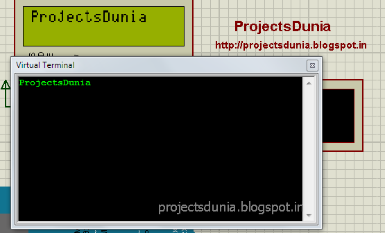
For getting the exact distance we multiply .034 in duration and then divide it by 2 because ultrasound travels forward and backward. At the end we use Serial.print() function to print the value in the virtual terminal.You can download the source code by clicking on the link.

Video Demonstration 

Hope you like this tutorial on the ultrasonic sensor. If you have got any problem using the ultrasonic sensor or its proteus simulation then feel free to comment below or if you have any suggestion about this tutorials and let me know by your valuable comments. 

How To Interface Relay With Arduino

By // 2 comments:
A Relay is an electromagnetically operated switch. Relays are used to control a circuit. Many relays consist a coil, a yoke, and an armature. When a current is passed through the coil, a magnetic field is induced in the coil which moves the armature and relay start its switching function. A normal relay has NO(normally open), NC(normally connected), COM and coil pin within it. A Simple one channel relay is shown in below image
relay driver interfacing
Relay
Required Components
For designing a relay driver circuit you will need following components 
  • Relay
  • 1N4007 Diode
  • BC547 Silicon NPN transistor
  • 10K Resistor 
Circuit Diagram
A simple relay driver circuit is shown in below image. Here we use an NPN BC547 transistor to drive the relay.Base current ought to be a lot of enough to turn on a transistor. A diode 1N4007 use among the circuit to protect the transistor from damage due to back emf. When relay is in off state, COM pin of 

circuit diagram of relay driver
Relay Driver Circuit 
a relay is connected to NC(normally connected) pin and when a small current start flows through relay coil then COM pin is connected to NO(normally open) pin.

NOTE: Change +5V  to +12V in the circuit 

Code for relay testing is same as for blink an LED so learn  how to blink an LED and test your relay driver circuit. Now using relay make some more cool projects using arduino like control your AC home appliances, turn ON/OFF a bulb and many more.

Hope you like this article and give your valuable feedback by commenting below or if you have got any problem then also comment below. 

How To Interface LDR With Arduino

By // No comments:
Hello, Friends hope all of you playing with your arduino and currently need to try to do another cool projects on arduino. Therefore, this tutorial is for you. During this tutorial, we interface LDR(Light dependent Resister) with the arduino board. It is very simple tutorials for arduino students, hobbyist, and beginners. Before going more we must find out how LDR is dependent on Light.

What is LDR 
interfacing ldr with arduino
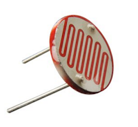
LDR(Light dependent Resister) or a photoresistor is a light dependent variable resistor that resistance decreases with the increase in the intensity of light. This gives an analog value so that it is connected to an analog pin of arduino board. A simple LDR is shown within the image and to buy an LDR click on the below image

Circuit Diagram
A simple circuit diagram is shown in the image. We won't use LDR directly within the circuit in order that a potential divider circuit is used with a 10K resistor. In this circuit one pin of LDR is connected to Analog pin A0 of arduino UNO and one pin is connected to ground(GND).

circuit diagram of LDR interfacing with arduino
LDR Circuit
Source code
Now connect your arduino board together with your PC and upload the given source code into the board. After uploading the code run your program and see the different value in your serial monitor.

LDR interfacing source code with arduino
LDR Code
Download:


Watch This Video:


How To Display Custom Characters On LCD Using Arduino

By // No comments:
We all are aware of custom characters used in the various display module.Heart, various style of smileys, arrow are the foremost usually used custom characters. Thus, during this tutorial, we are going to learn how to display custom characters in LCD using arduino UNO board. This project is done by using of arduino UNO board and 16*2 LCD module.

how to display custom character in lcd using arduino
Custom Character Display
It is assumed that reader knows how to interface LCD with arduino and how to install arduino software.We can generate a completely different style of the custom character using the below pixel array shown in the image. 
use of pixel array of lcd
Pixel array
the custom character shown below that is used in our program to generate the smile type character:
         {
                0b00000,
                0b00000,
                0b01010,
                0b00000,
                0b10001,
                0b01110,
                0b00000,
                0b00000
              };

Circuit diagram:
circuit diagram of display custom character in lcd
Circuit Diagram
Source Code:


Download:


Video:


Interfacing Push Button Switch to Arduino

By // No comments:
There are many electronic circuits can be used to interface with the device in the real world using switches as inputs. The simplest type of interfacing device is push button switches due to its low price and simple interfacing with any kind of electronic circuit. Push button switches are widely used in many electronic projects so knowledge of their interfacing is extremely essential in designing projects. So during this article, we learn how to interface push button switches with arduino. I hope you have knowledge about Arduino Board and led interfacing. Push button has four terminal and its allow current to pass through it when you press it down. 
push button interfacing
Push Button
Here we use PULL-UP or PULL DOWN resistor while using switches. PULL-UP register is a register connected between power supply and connector to give an electricity on certain condition.To understand the working of Pull-UP resistor look the image how its work.
working of pullup resistor
Pull-Up Resister
REED THIS ARTICLE  Interfacing LCD With Arduino UNO

Circuit Diagram
circuit of push button interfacing
Circuit Diagram
Source Code
code of push button interfacing
Source Code
Download

Download source code and circuit diagram file from here

Video


Controlling LEDs With PC Using Arduino

By // 1 comment:
Wireless communication plays a very important role within the communication system. We may be able to send data from one point to another point simply through wireless communication. There is such a large option available for the wireless communication like Bluetooth, Wi-Fi etc. In this article, we concern only in Bluetooth. Bluetooth is a standard wireless technology which transfers the information over very short distances. It is assumed that you just ought to knowledge to How To Send Serial Data From Arduino To Laptop or PC and How To Receive and Send Serial Data Using Arduino Board

Controlling led via PC/Laptop

After Reading this article you will be able to control LED via your PC/Laptop. For controlling the led we use arduino board Introduction to Arduino Board

Circuit diagram:

Here we use three led blue, green and red that are connected to pin no. 10,9 and 8 of arduino board respectively. We also connect an LCD display module to arduino board. read this post for Interfacing LCD With Arduino UNO. All other connection for controlling led via PC is shown below image

circuit diagram for led control
Circuit Diagram
Program:

// ProjectsDunia
// http://projectsdunia.blogspot.in
// Our Facebook Page http://facebook.com/projectsdunia

//  control LED with your PC


#include <LiquidCrystal.h>

// initialize the library with the numbers of the interface pins
LiquidCrystal lcd(12, 11, 5, 4, 3, 2);
int blue_led=10;
int green_led=9;
int red_led=8;
int store=0;
void setup()
 {
    // set up the LCD's number of columns and rows: 
  lcd.begin(16, 2);
  // initialize the serial communications:
  Serial.begin(9600);
  pinMode(blue_led, OUTPUT);
  pinMode(green_led, OUTPUT);
  pinMode(red_led, OUTPUT);
  }
void loop()
{
  // when characters arrive over the serial port...
  if (Serial.available()) 
  {
    // save the data 
    store=Serial.read();
    switch(store)
    {
      case '1':
      lcd.clear();
      digitalWrite(blue_led,HIGH);
      lcd.write(" Blue_LED ON ");
      break;
      case '2':
      lcd.clear();
      digitalWrite(blue_led,LOW);
      lcd.write(" Blue_LED OFF ");
      break;
      case  '3':
      lcd.clear();
      digitalWrite(green_led,HIGH);
      lcd.write(" Green_LED ON ");
      break;
      case '4':
      lcd.clear();
      digitalWrite(green_led,LOW);
      lcd.write(" Green_LED OFF ");
      break;
      case '5':
      lcd.clear();
      digitalWrite(red_led,HIGH);
      lcd.write(" Red_LED ON ");
      break;
      case '6':
      lcd.clear();
      digitalWrite(red_led,LOW);
      lcd.write(" Red_LED OFF ");
      break;
      
    }
  }
}
  
Download:

LED control file

Video:


If you have any question, leave a comment below, Thanks for reading this article.If you like this article then support us by subscribing our youtube channel and like our facebook page.


How To Receive and Send Serial Data Using Arduino Board

By // No comments:
Serial communication is the easiest way to communicate with the peripheral device in embedded system. Thus, during this article, you may be able to learn the way to receive and send serial data from the arduino board. If you are beginner then first read this Introduction to Arduino Board and How To Send Serial Data From Arduino To Laptop or PC before moving on this article.
serial communication virtual terminal monitor
Arduino ide has such a big amount of inbuilt function for serial communication and detail of some function are here  How To Send Serial Data From Arduino To Laptop or PC. During this article, we tend to use some additional function that facilitates us to receive the serial data from the serial port. These functions are Serial.available(), Serial.read(), Serial.write whose explanation are given below:

1: Serial.available()

This function is always used before the Serial.read() function. This function returns always a positive value once reception is complete. This function is used for whether or not entire data is received.

2: Serial.read()

This function is used to read the received data from the serial port. We will save received data in any variable for any condition to ascertain.The variable could also be integer or character.

3: Serial.write()

This function is same as Serial.print() and Serial.println() explained in How To Send Serial Data From Arduino To Laptop or PC. This function returns the data to the serial port of the arduino.

Circuit diagram: 

circuit diagram for serial communication
Circuit Diagram
Code:
code for receiving serial data from laptop
Code
Download:


Video:


If you have got any question concerning this article then be happy to comment below or contact us via social network like facebook 

How To Send Serial Data From Arduino To Laptop or PC

By // 6 comments:
Serial Communication plays important role within the communication system. All micro-controller should have serial communication port.Serial communication provides a text-user-interface(TUI). One will use serial port of microcontroller to send data serially to laptop/PC or receive data serially from laptop/PC.Here we use arduino board to communicate with the laptop. Arduino board have a minimum of one serial port to communicate known as UART and USART. It communicates with digital pin 0 and 1 of arduino refer to as RX and TX pin as well as with the computer via USB.

send data to pc with arduino
Virtual Terminal
Interfacing LCD With Arduino UNO

Arduino has a built-in function for serial port thus there is no need to go into register detail. In Arduino IDE, one can easily call the serial function for the serial port and job is finished. A simple connection for serial communication is shown below
 serial communication connection
Connection For Serial Communication
For serial communication with arduino, we have to use three function known as Serial.begin(), Serial.print(),Serial.println(). Their function is as follows

1: Serial.begin()
To initialize the serial port for the communication we use this function.In this function baud rate is used to initialize the serial port. Here we have used 9600 baud rate for the communication.

2: Serial.print()
This function helps to send serial data to the device connected to the serial port of arduino board. Using this function we are able to send both ASCII and string to the device.
3: Serial.println()
This function is used to print the send data into a new line and all the function is same as the previous function.
Circuit diagram:

circuit diagram for serial communication
Circuit Diagram
Code: 
Download the hex file from below.this image is just for showing. we connected a led to pin no 5 of arduino board therefore whenever data is sent to laptop/PC led can blink. 

code for serialcommunication
Code
Download:


Video:


How To Interface Seven Segment Display With Arduino

By // 3 comments:
A seven segment display is an electronic display device for displaying numeral. Seven segment display are widely used in the digital clock, TV, electronic meter and other electronic devices which display numerical value. Simple seven segment display image is shown below:

seven segment display image
seven segemnt pin diagram
Seven-segment Display may be used in two modes:
1: Common anode ( all of the positive terminal are connected) 
2: Common cathode (all of the negative terminal are connected)
In this tutorial, we tend to use common cathode mode to display the numerical number.


Circuit diagram

Arduino pin 2,3,4,5,6,7,8,9 is directly connected to a,b,c,d,e,f,g,h data pin of seven segment display as shown in image:

seven segment circuit diagram with arduino
Circuit Diagram
Program
Code for one digit count down timer from nine to zero is written in arduino ide as shown in image.

code for seven segment interfacing with arduino
Code
Copy or download the code and paste it within the empty sketch of arduino ide and so compile the sketch and upload it to your board. Now enjoy count down timer using seven segment display. 


Download


Video


If you have got any problem then feel free to comment in box or connect us with social media facebook and google+

How to Use A Temperature Sensor With Arduino

By // 8 comments:
A thermometer is a device measures the temperature. A Thermometer consists a temperature sensing element that senses environment temperature and provides the result to the suitable devices. During this article, you may tend to learn to make a digital thermometer using LM35 temperature sensor and LCD module display.For LCD interfacing with arduino read this article Interfacing LCD With Arduino UNO  

LM35 :

LM35 temperature sensor
LM35 Temperature Sensor 
LM35 is a temperature sensor that is employed to measure the temperature. It has three terminal Vcc, Output, Ground as shown in the above image 
The range of the LM35 temperature sensor is from -55 'C to +155 'C. The output range varies by 10mV to each fall and rise in temperature. Circuit diagram of Digital Thermometer using LM35 temperature sensor with arduino UNO is shown below: 

Automatic Temperature Fan Speed Controller 

Circuit diagram

It has a very simple circuit. The output terminal of the sensor is connected to the analog pin A0 of arduino board. Vcc and GND pin of the sensor are connected to the power supply and GND respectively. 
circuit diagram of digital thermometer
Digital Thermometer Circuit Diagram


Program
arduino code of digital thermometer with LM35
Code For Digital Thermometer
Download


Video


How To Interface LCD With Arduino UNO

By // 1 comment:
LCD module is incredibly common part at intervals embedded system design.16*2 alphanumeric LCD module is most generally used  alphanumeric LCD module at intervals the embedded system. LCD module employed in wide selection of applications well as consumer devices such as DVD player,television,clock,gaming devices and watches.There are 16 pin available and may be operated
in 4-bit and 8-bit mode. Here we have tendency to victimization LCD module in 4-bit mode. The schematics of simple 16*2 LCD module is shown in below image

LCD Display

The name and function of every Pin of LCD module is given below:

Pin1(Vss): Ground pin of LCD Module

Pin2(Vdd): +5v supply is given to this pin

Pin3(Vee): Adjust contrast of LCD. +5v supply is given for full contrast.


Pin4(RS): Resister select pin in LCD module. There are two register command register and data register. Logic High for data register and Logic Low for command register. 

Pin5(R/W): Read/write modes.Logic High for read mode and Logic low for write mode.

Pin(E): Enable pin. This pin for enabling LCD module.

If you don't have LCD module then you can purchase from here at very cheat price LCD

Pin7(DB0) to Pin14(DB7): Data pins. command and data are put on this mode.

Pin15(LED+): Anode of back light led.

Pin16(LED-): Cathode of back light led.

Circuit Diagram
circuit diagram of lcd interfacing
Circuit Diagram

Program

code for lcd interfacing with arduino
Code

Library function "liquidcrystal.h" is employed for displaying character on LCD module. It is available in the arduino example and accessed through the "Import Library" within the sketch tab of the arduino ide.

Download:


Video Demonstration 


How To Blink a LED Using Arduino

By // 2 comments:
LED is Light Emitting Diode play a really necessary role within the embedded system design. A Diode is a two terminal component within which current flow from the positive direction to negative direction. During this article, we tend to find out how to interface an LED with an Arduino. Simple LED is shown in the image.
simple LED Projectsdunia
LED
In this tutorial, I will able to show you to run three LED at the same time using your Arduino board.
 Component Required:
  • Arduino UNO Board
  • 3 LED
  • Wire
  • Power Supply

Circuit diagram:
Circuit diagram of interfacing LED with Arduino board for running three led at the same time is shown below:

circuit for interfacing of 3 led with the arduino board
Circuit Diagram

NOTE: Add a current limiting register in series with led to prevent it from damage.
Positive(anode) terminal of the LED is connected to the 11,12 and 13 pin( digital pin) of the Arduino board as shown within the circuit diagram. Negative terminal of the LED is connected to the Ground.The code is written within the Arduino IDE as shown in below:

Arduino program for the led interfacing with arduino board
Code


About the program:
In this program we tend to use three digital pin 11, 12 and 13 of the Arduino board that are name as x,y,z respectively. The "void setup()" function runs once at a time within the program. In this function we tell to program that led is connected as output using the "pinMode" keyword. second function "void loop()" within the program runs over and over repeatedly.In this function we tend to write our desired code for the Arduino board.

blink three led at a time

Download:


Video:

How to Install An Arduino Library For Proteus

By // 7 comments:
Arduino is a terribly famed microcontroller board. Each engineer, student or hobbyist needs to verify it projects design in real time environment before assembling it on real hardware. Proteus is that the initial alternative for this however in Proteus software there's no library available for the Arduino.
Therefore, during this article, you find out how to verify your Arduino project in Proteus by using the Arduino library.

How to Install An Arduino Library For Proteus
  1. First of all, you have got to download the Arduino library for the Proteus software. For this, you will be able to search on Google or download from here.
  2. After downloading the file extract the .rar file and copy the two file name as Arduino.idx and Arduino.lib 
  3. Now paste the copied file in the subsequent path 
    Drive C >> Program files >> Labcentre Electronics>> Proteus 7 Professional>>Library

If you want to buy an Arduino development board then you can buy your first Arduino board from here ARDUINO

Now open Proteus software and search for the arduino within the pick device wizard.You will see the subsequent image
install arduino library for proteus
Now you will be able to verify your projects code and circuit supported the arduino board by victimization the Proteus software. If you got any problem then be happy to write down within the below comment box or by connecting to this blog on varied social media pages.


DOWNLOAD

How To Install Proteus Software On Windows

By // 3 comments:
Proteus is an Electronics design and simulation software developed by the Labcenter Electronics. Engineering student or hobbyist will design and check their project on Proteus software before assembling it on hardware. To install  Proteus software on windows follow the below instruction:

How To Install Proteus Software On Windows
Download the Proteus software setup from here and double click on the setup.exe file as shown in below image
insrall crack version of proteus software
Setup

After few minute step can complete here you'll install the license key that ought to be valid for the Proteus software. Here you choose "use a locally installed license key". Currently, one in all two window is open. It'll be either window with already installed key or no key installed. If you get a window with an already installed key then simply click on the "next" and at the last click on the end to finish the installation.

How To Interface LCD With Arduino UNO

Currently, if you get a window with no key installed then initial download the license key from here.

licence of proteus software
Licence

Browse the on the top of the downloaded file in the window and so click on the "find all keys" and once few minute click on the "close". CCurrently,Proteus software is install on your window double click on the Proteus application to open the Proteus software.
     
   Note:

  • Disable your antivirus program before installing the Proteus software on your windows

Now run your Proteus software application and revel in your design simulation of various PCB design and code.

DOWNLOAD:

Proteus

Licence key