Showing posts with label 555 IC. Show all posts

Automatic Street Light Controller Circuit Using LDR And 555 Timer IC

By // 54 comments:
We are living in the world where everything goes to be automatic from your washing machine to your ceiling fan. Street lights are one of those examples of the automatic world. Automatic street light are those light which needs no manual operation to gets turn ON and turn OFF. Did you ever try to make such kind of street lights that gets turn ON and turns OFF automatically? In this article, we are going to make automatic street light using LDR and 555 timer IC.

List of Components  
  1. 555 Timer IC
  2. LDR
  3. LED
  4. Potentiometer
  5. Resistor 1* 1k ohm 
  6. Resistor 1* 220 ohm
  7. 9V Battery
  8. Printed Circuit Board(PCB) Or BreadBoard 
Circuit Diagram
A very simple circuit diagram of automatic street light is given below. 
automatic street light controller circuit using ldr
Automatic Street Light Controller Circuit

Principle and Working of Automatic Street Light Controller

555 Timer IC is the main part of the circuit that works as a comparator. All the working of this circuit depends on the working of the 555 timers Ic.To know more about 555 times IC read this article Working of 555 Timer IC. In this circuit pin, 3 produce output which has just two states high and low. Output goes to high when  trigger pin  is at a lower level than the 1/3rd level of the power supply voltage and output goes low when trigger pin 2 is at above then 1/3rd  of the power supply voltage. In this circuit pin, 4,6 and 8 are connected to the power supply. Here we use LDR to detect the presence of light which is formed a potential divider circuit with the help of 1k ohms resistor. LDR is a special type of resistor whose value depends on the light. Read this article to know How LDR Works. The output of this divider circuit is given to trigger pin of the 555 timer IC. 

In this circuit, we use a simple LED to know how the whole circuit works. You can also connect as much led as you want by using the transistor or you can connect a Relay to control high voltage electrical bulbs. 

You must use caution while connecting Relay to this circuit because its may be danger and as different bulb have different wattage.

Video Demonstration of Automatic Street Light Controller


555 Timer IC: Introduction, Working and Pin configuration

By // No comments:
One of the most versatile linear integrated circuit is 555 timer. 555 timer IC was first introduced in early 1970 by  Signetics Corporation.555 timer IC is incredibly low cost and popular timing IC that is used by electronics student, hobbyist for generating timing delay and pulses. Mono stabale and astable multi vibrators is that the most correct example of its application. With the exception of this it's conjointly used for oscillations, waveform generators, analog frequency meters, voltage regulators, digital  probes, tone generation, frequency divider and lots of others.This device is obtainable as 8-pin mini Dual-in-line package(DIP)  or 14 pin Dual-in-line package(DIP) that consist 25 transistor,16 resistors, 2 diode.

PIN CONFIGURATION OF 555 TIMER IC
555 timer ic pin configuration
8-Pin DIP 555 Timer IC

Pin 1: Ground   This pin is used to measured the all voltages.

Pin 2: Trigger   Negative going pulse is applied to this pin whose dc level is greater than 1/3 times                                VCC. Thus comparator 2 output goes low. The output remains high as long as                                      trigger terminal is held at low voltage.

Pin 3: Output    Output pin is available to connect the load.There are two ways of connecting the                                   load either between pin 3 and ground or between pin 3 and +Vcc pin of 555 timer                                 IC.

Pin 4: Reset      555 timer can be reset by applying a negative pulse to this pin.

Pin 5: control voltage  To change the threshold voltage and trigger voltage an external voltage is                                               applied to this pin.

Pin 6: Threshold  SR flip flop is reset when voltage at this pin is greater than 2/3 Vcc.

Pin 7: Discharge   This pin is directly connected to the collector of transistor.When transistor is off                                     this acts as a open circuit and when transistor is on, acts as a shot circuit.

Pin 8:   A Supply voltage is applied to this pin that ranges from +5v to +18v with respect to                              the ground.

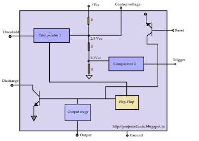
Block Diagram of 555 Timer IC

555 timer ic block diagram image
555 Timer IC Block Diagram

The 555 timer IC work as a mono-stable multi-vibrator and astable multi-vibrator. A voltage divider circuit is internally connected to the Pin 8 and Pin 1 of 555 timer IC. This circuit hold positive non inverting terminal of comparator at 1/3Vcc and negative inverting terminal of comparator at 2/3Vcc. The output from each comparator is connected to the input of the SR Flip-Flop. The output from the SR Flip-flop acts as a switching stage to drive the Load.

555 Timer IC has three operative modes known as:
1: Monostable
2: Astable
3: Bistable

To Know additional concerning 555 IC Click on this 555 Data sheet.